Building a Custom Dashboard
Table of Contents
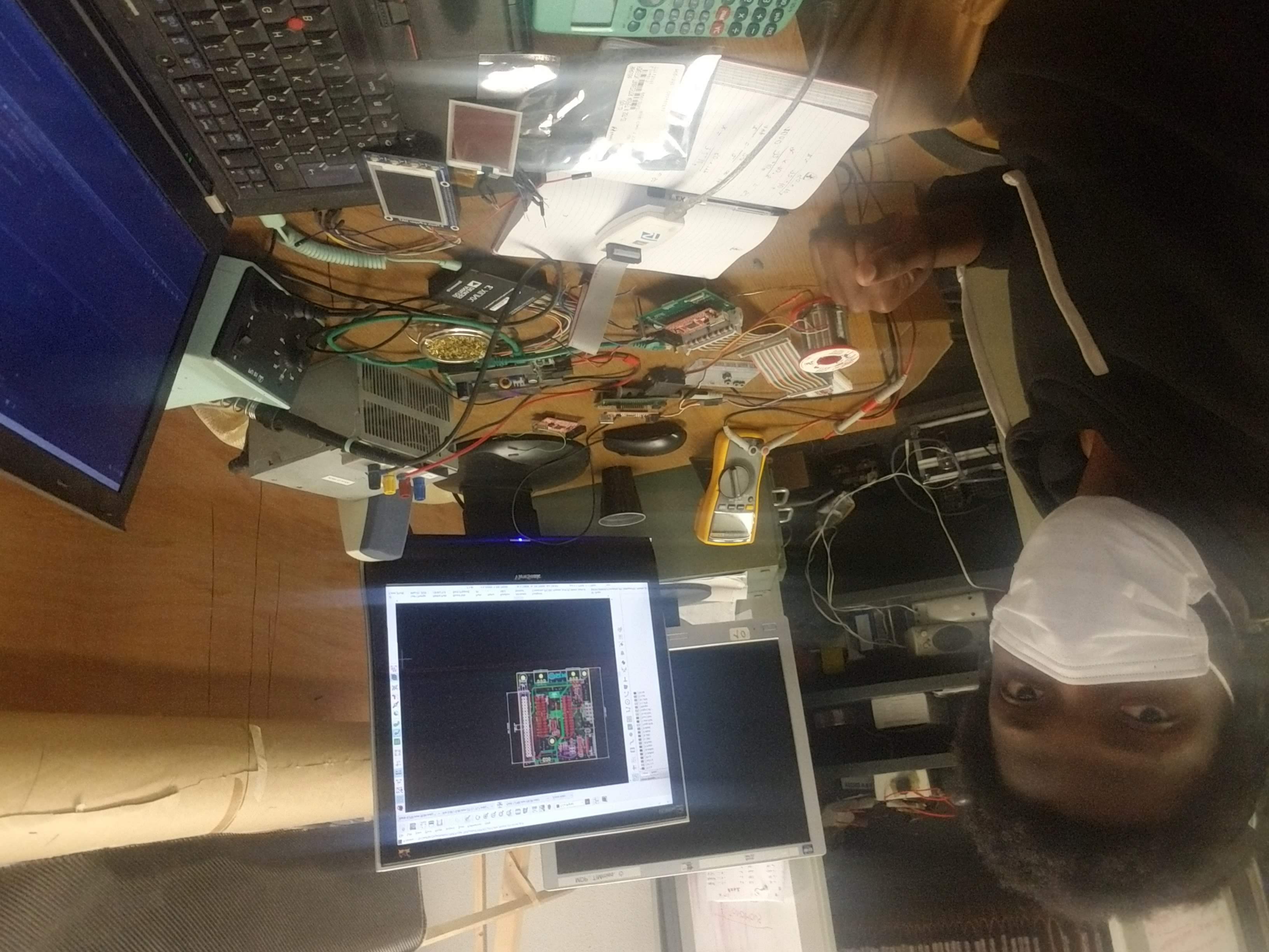
who is deeply into electronics !
Now, let me guess,
- he owns a ThinkPad,
- spends all his free time in a basement1
- and work on circuits and programming using a 4:3 aspect ratio screen.
You don’t need to stretch your imagination too far…
That’s me, fully immersed in creating the Dashboard for the TIM.
Here’s the corrected version:
What did we already have?#
Between the car and the driver, for control and feedback, the interface the team was using consisted of two main parts: the steering wheel and the magic plate.
An STM32-based board was embedded in the steering wheel, while a PIC18 brought the magic to the magic plate.
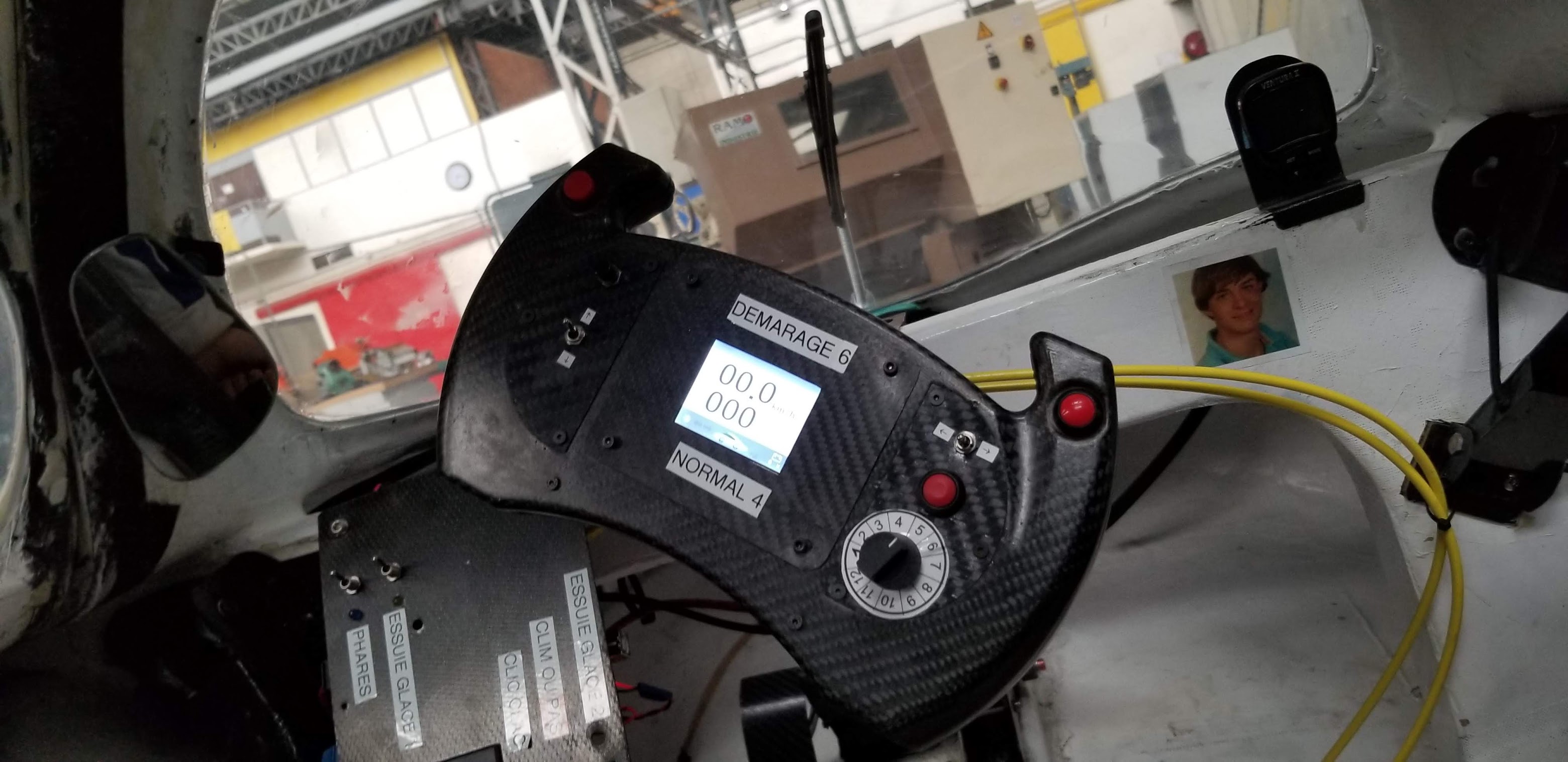
On the steering wheel, there was a color LCD screen that displayed the car’s speed, the engine temperature, the state of the signals (whether you’re turning left or right, and if the headlights are on or off), and the position of the controls. The steering wheel also had buttons for acceleration, signaling (left/right), front and rear lights, and the horn.
As for the magic plate, made from a carbon fiber sheet, it had two switches for controlling the windshield wipers—¿Por qué no los dos?—one for the air conditioner2, another for the headlights, and a special magic switch to reset the system whenever a “magic overload” disrupted the controls.
What’s better than LEDs with their low power consumption on the magic plate? It’s rhetorical… nothing is the right answer 😏.
What Were the Needs?#
We needed to reduce complexity and create a new dashboard for the upcoming vehicles. Here’s why:
- The screen on the steering wheel was outdated and no longer available.
- The build files for the system were missing.
- A new car was in production, requiring a new interface.
- We aimed to simplify the dual-system setup, returning to the wisdom of the “smol brain” engineer3.
What did we want to build?#
Here are our objectives:
- E pluribus unum 4: One system instead of two
- Lower power consumption
- Improved reliability
- Enhanced updatability
- Increased configurability
And here’s what we’d like the finished product to be:
I started by pulling out the Ferrari design notebook to sketch out my take on their steering wheel (though admittedly, my sketch is a bit rough):
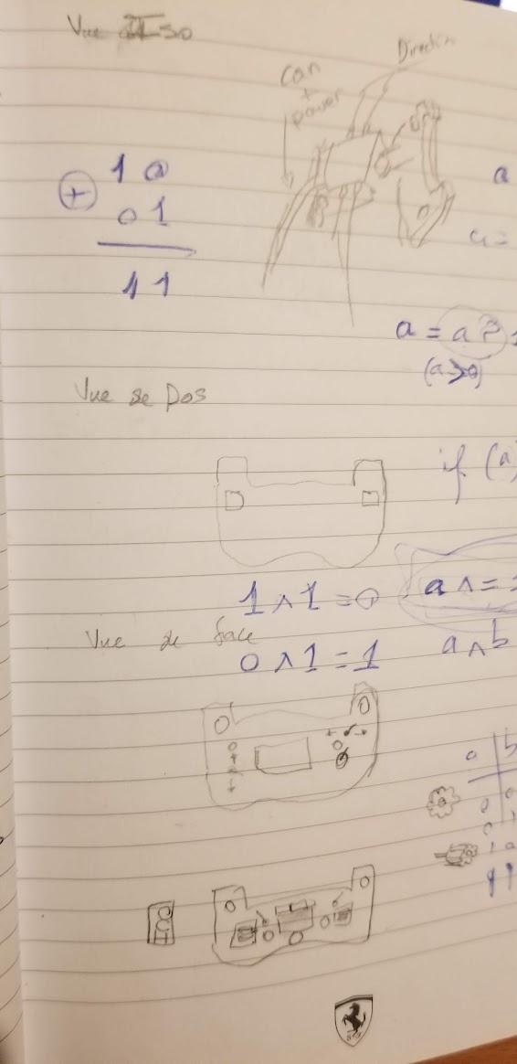
To better visualize the system—since the sketch might be a bit confusing—I also created a detailed design document.
What was the plan?#
Specifications:#
Essential Requirements:#
- Display actual speed on screen.
- Control headlight (on/off).
- Signal turns (left, right, off).
- Operate windshield wipers.
- Display brake light status on screen.
- Adjust wiper speed.
- Select power level.
Optional Requirements:#
- Set speed limit.
- Display set speed limit on screen.
- Switch between forward and reverse driving modes.
- Turn the car on/off.
- Configuration interface to choose between different modes and car types.
Out of Scope:#
- Horn (48V … This is not the kind of power I want on my electronics).
Who?#
Sofiane Aouci and I were responsible for developing the dashboard. We started strong by leveraging this public repo .
As the Software Lead (Sensei), Sofiane handled the displays. To balance low power consumption with reliability, he worked on hacking an ePaper display to enhance its refresh rate and wrote software for to drive a LCD screen in case we chose to go that route.
As the Software Second (Padawan), I managed the remaining software tasks. Why did the Padawan have all the remaining work ? Because the tasks were simpler, of course! Plus, it was a great learning experience.
Furthermore, as the Hardware Lead, must of the remaining software neeeded was closely coupled with the software that I had to write to test the board.
What?#
Software#
The software architecture followed the Model-View-Controller (MVC) pattern. We made this choice so that, using STM32CubeIDE to program an open source header board STM32-H103 from Olimex we could acheive our reliability, updatability and configurability goals.
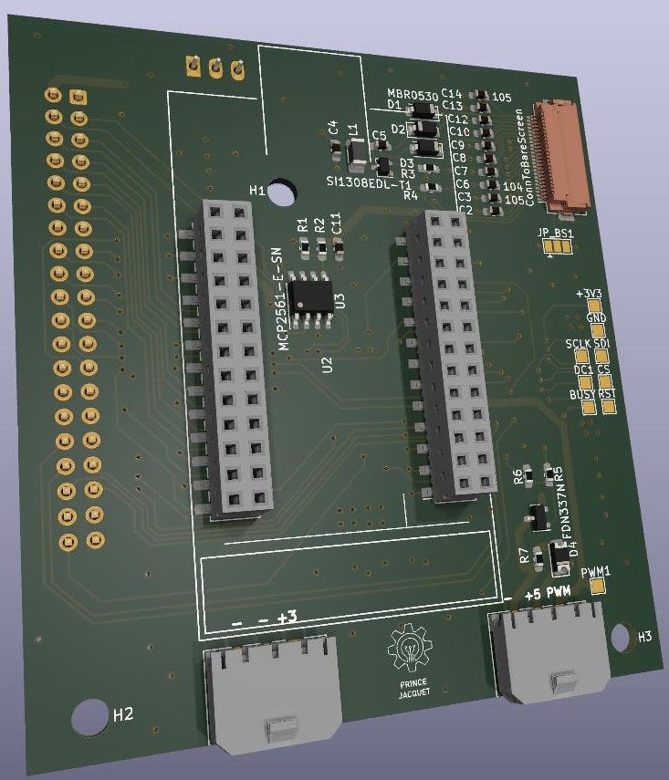
Hardware#
I initially used a hardware version management service,inventhub(hardware versions management), but unfortunately, the server seems to be down now.
Our hardware was an STM32-based system with multiple inputs/outputs, CAN communication, PWM output, raw screen circuitry, SPI, and more. The deliverables included the Interface Control Document (ICD), user manual, pinout diagram, and the fully tested board.
How?#
Software#
Here’s a checklist of what is typically expected in software development and what we accomplished:
1. Requirements Analysis
- Understand the Problem: The requirements were understood and addressed.
- Hardware Specifications: Confirmed that the STM32F1xx series microcontroller, its associated peripherals, and other external hardware were appropriate and sufficient for our application.
2. System Design
- Architecture Design: Chose the architecture best suited for our application and goals—Model-View-Controller (MVC).
- Module Design: Designed and separated modules. Interaction between modules was based on their roles and the project’s needs, utilizing DMA and interrupts as much as possible.
- Interface Design: Defined the interfaces between the LVGL library (
lvgldirectory) and the CAN communication, including how data is exchanged in the car.
3. Development Environment Setup
- Toolchain Selection: Used STM32CubeIDE, correctly configured for the STM32F1xx microcontroller.
- Hardware Setup: Verified that our development board and hardware setup worked correctly for flashing and debugging. Ensured that all tools functioned as expected.
4. Firmware/Software Development
- Low-Level Programming: Developed drivers and low-level code where necessary, using the HAL library for other STM32F1xx-related code.
- Application Programming: Wrote application logic in the
Coredirectory, including hardware initialization, task management, and main application functionality. - GUI Programming: Implemented and integrated LVGL functionalities located in the
lvgldirectory.
5. Simulation and Debugging
- Simulation: Not performed due to time constraints and simplicity of the application. The software and application were deemed straightforward enough.
- Hardware Debugging: Used debugging tools available in the IDE to test and troubleshoot the software on actual hardware.
6. Testing and Validation
- Unit Testing: Not performed. Perhaps Sofiane did some unit testing, but you would need to ask him 😅.
- Integration Testing: Tested integrated modules to ensure they worked together as expected.
- System Testing: Conducted end-to-end testing of the complete system.
- Validation: Confirmed that the system met all* requirements and performed correctly in various scenarios.
7. Optimization
- Performance Optimization: Optimized code for execution speed and memory usage; crucial for the project’s success.
- Code Size Optimization: Applied compiler optimizations to reduce code size, which was essential due to limited flash memory on the embedded system.
- Power Optimization: Implemented power-saving features based on the system’s requirements.
8. Deployment
- Final Build: Generated the final firmware build.
- Programming the Device: Flashed the firmware to the device.
- Configuration and Calibration: Performed necessary configuration and calibration directly on the target. Made the JTAG connector accessible to avoid needing to open the steering wheel for flashing or debugging.
All that remains is for the TIM team to handle ongoing maintenance and updates. They’ve been doing an excellent job.
- 9. Maintenance and Updates
- Bug Fixes
- Feature Updates
- Long-Term Support
- 10. Compliance and Certification (Not applicable in our case)
- Regulatory Compliance
- Certification
- 11. End-of-Life Considerations
- Decommissioning
- Legacy Support
Hardware#
For a detailed guide on hardware development, you can refer to this onboarding document, a relic which I created to assist new college students in understanding PCB design and manufacturing in practice.
Below is an overview of the hardware development process, presented as a checklist similar to what I used for the software. This provides a structured view of the steps involved and what was accomplished.
1. Define Requirements and Specifications
- Application Requirements: Figured out what our embedded system needed to do and what it’s all about.
- Performance Requirements: Set some loose goals for speed, power consumption, and processing power—just enough to get the job done without setting the world on fire.
- Interface Requirements: Decided on the inputs, outputs, and all the communication magic.
- Environmental Conditions: Accounted for everything from temperature and humidity to vibrations and pesky RF noise.
2. Select Components
- Microcontroller/Processor: Picked out a microcontroller or processor that was just right for our needs (hello, STM32 Olimex board!).
- Memory: Chose the right mix of RAM, ROM, and Flash memory.
- Power Supply: The car’s power system was already set, so it handled our voltage and current needs like a champ.
- Sensors and Actuators: Identified and picked sensors, actuators, buttons, and screens.
- Communication Modules: Selected modules for communication protocols (think UART, SPI, I2C, CAN).
3. Design the Circuit
Schematic Design: Created a detailed schematic diagram using CAD tools (KiCad, Eagle).
- Component Selection: Placed components in the schematic, made a bill of materials, and bought everything while considering delivery times and future availability.
- Power Management: Designed circuits for power distribution and regulation. A simple linear regulator and a DC/DC converter did the trick.
4. PCB Design
- PCB Layout : Converted the schematic into a PCB layout, arranging components and routing traces.
- Design Rules Check (DRC): Made sure the PCB design met all the rules and constraints—no room for errors here!
- Thermal Management: Factored in thermal aspects, using the most filled zones possible to avoid overheating.
5. Prototype Development
- Fabrication: Sent PCB design files to manufacturers like Aisler for European builds and JLCPCB for speedy, budget-friendly options.
- Assembly: Assembled components onto the PCB manually, though automated assembly services are highly recommended if you can swing it.
- Testing: Tested the prototype. And yes, occasionally discovered that some wiring might be mirrored and had a good cry about it.
6. Firmware Development
- Bootloader: Not needed here—we’re going straight to raw C on the microcontroller, no OS required.
- Low-Level Drivers: Wrote low-level drivers for all peripherals and components.
- Application Code: Developed the application code that made the hardware tick.
- Debugging: Used debugging tools to test and troubleshoot the firmware on actual hardware.
7. Integration Testing
- Hardware Integration: Ensured all hardware components played nicely together.
- System Testing: Put the integrated system through its paces to make sure it worked as expected in the real world.
8. Documentation
- Design Documentation: Created detailed documentation of the hardware design, including schematics, PCB layout, and component specs.
- User Manual: Not necessary for our end-user engineers; they can figure it out from the design docs.
- Maintenance: Same deal—if the team can rebuild it, they can also maintain it.
The following is for product that intend to get on the market. Not applicalble for our use case.
- 9. Optimization
- Performance
- Cost
- Size and Weight
- 10. Manufacturing and Production
- Design for Manufacturability (DFM)
- Supplier Selection
- Quality Control
- 11. Compliance and Certification
- Regulatory Compliance
- Certification
- 12. Deployment and Support
- Deployment
- Support
- 13. End-of-Life Considerations
- Decommissioning
- Legacy Support
There you have it!
Each step is crucial for crafting reliable and functional hardware for embedded systems, ensuring everything works seamlessly in its intended environment.
What is the result ?#
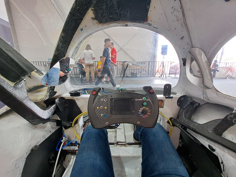
The process was slower than expected, with several challenges along the way. But in the end, we created a functional dashboard that met the project’s needs.
While there’s always room for improvement, particularly in streamlining the process and better planning for potential delays, the project was ultimately a success.
Thanks to a fantastic counterpart and an incredible team, we finally managed to get the dashboard installed and winning awards in the car.
There are no articles to list here yet.